Every once and a while I come across a problem which has a fairly expensive solution where a much simpler and cheaper one will do. In this post I’m going to try to give a quick summary of one such problem, the project I undertook to solve it, and how I saved around $30 while learning a thing or two about circuitry and product design along the way. I also hope that anyone trying to build a similar project will be able to find this post and gain some info to help them along their way.
What did I need?
In my apartment I have one speaker system and two devices which I use for audio playback: my desktop computer and my Echo Dot. When I wanted to switch between the two devices I’d need to move the speaker input jack manually from one device to another. This practically negated the convenience of controlling my music (which I have constantly playing when I’m home) through Alexa. After some time, I got fed up and decided to begin looking for a solution.
After a quick search, I determined I could solve this problem with an audio mixer which accepts input from two or more 3.5mm headphone jacks and outputs audio through another 3.5mm jack. A quick search of online retailers revealed that I’d have to pay at least around $35 for such a device. All of the devices had features which I did not need (like balance and gain, which I can adjust on my input devices), and many of them used 1/8” jacks rather than 3.5mm, making adapters necessary.
I’m pretty familiar with electronics and circuitry work, but audio signal circuits were something which I was quite unfamiliar with. However, given that audio is transmitted by analog signal over 3.5mm connections I intuitively figured I should just be able to merge the two signals together.
I started doing some research, and quickly came across a number of projects which use amplifier circuits and ICs in order to perform signal mixing (largely for the purpose of controlling the gain of each channel), but remember, the name of the game here is cheap. I wanted to try and get this done with as simple a circuit as possible. So I narrowed my search to include only circuits using passive components. I came across a very helpful Instructable (here) and several posts on the subject (here and here) which all suggested that the passive mixer circuit I envisioned would work just fine, so long as there were resistors on each audio channel going into the mix.
The major drawback of this setup is that as we increase resistance in the circuit we will reduce the output gain (volume) of the mix. Because I am feeding my audio signal into a speaker system with its own built-in amplification circuits, however, this was not at all a problem.
The build
I settled on building a mixer with two 3.5 mm inputs and one 3.5 mm output (just enough for what I needed). I used the following parts and tools for this build:
- Parts
- 3 x 3.5mm jacks ($3 for 20 on ebay)
These come in many different shapes and sizes, so you may need to adjust the case model - 4 x 1k Ohm resistors
- 1 x Screw
- Wire
- Solder
- PLA Filament
- 3 x 3.5mm jacks ($3 for 20 on ebay)
- Tools
- Soldering Iron
- 3D Printer
After I received the 3.5mm jacks in the mail, I was able to get to work designing a 3D printed enclosure to encase the circuit and protect it from damage. I constructed a case in two parts: a base which has slots for each of the headphone jacks and a lid which holds the headphone jacks in place (secured using a screw) with a space for the wiring to run. You can find the STL files for the print here.
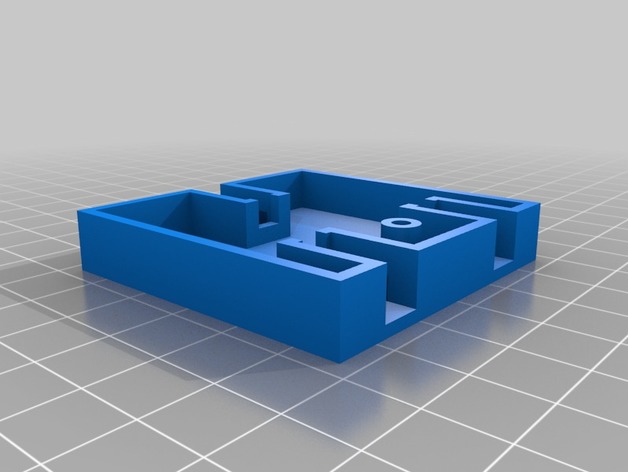
Case Base 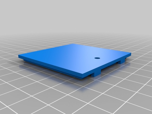
Case Lid 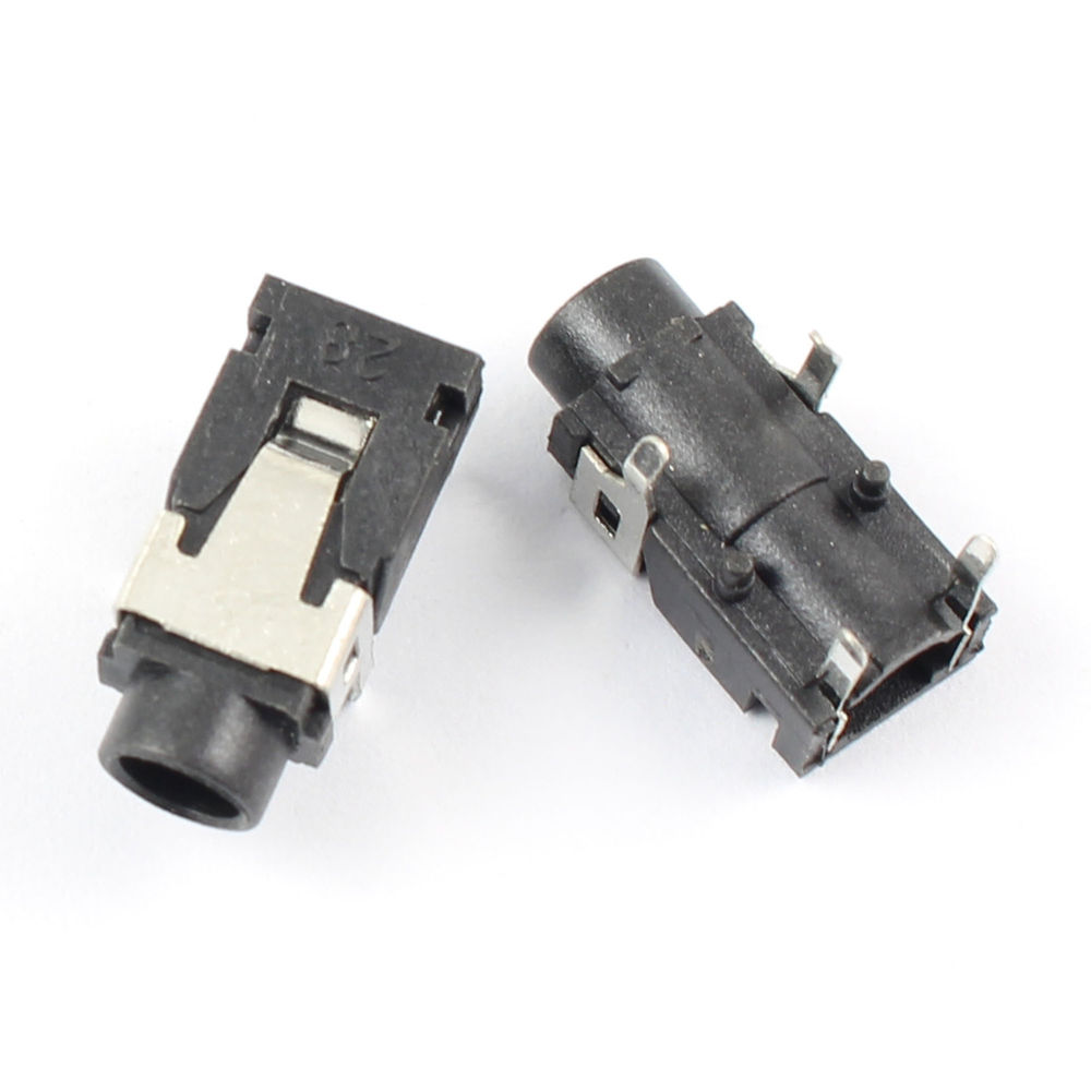
3.5mm Headphone Jacks
After the print was finished it was time for the wiring, by far the most difficult part of this project. Each 3.5mm headphone jack needs 3 terminals (though extra pins may be included on the jack): the left + right audio channels, and a common ground.

The goal was to pass the signal of each audio channel (left or right from each input jack) through a 1KΩ resistor into a common line to the respective pin on the output audio jack. The ground lines are simply connected by a wire. This is not too difficult to diagram, but soldering it together proved a bit more challenging.
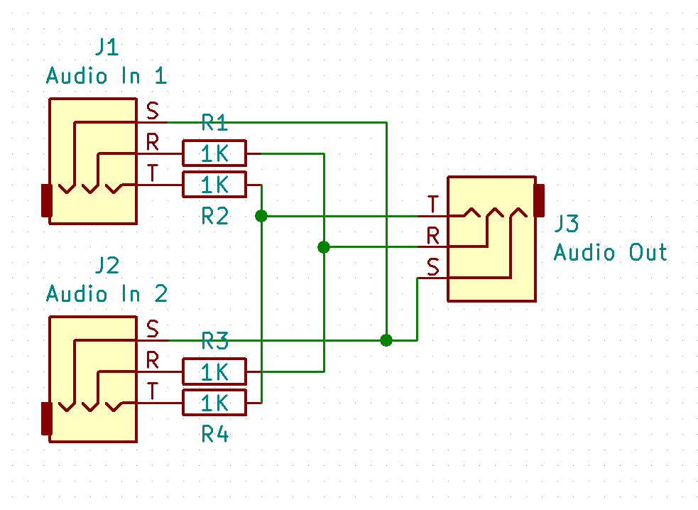
Circuit diagram designed in KiCad
The trick with constructing the circuit is connecting all of the resistors, wires, and pins together without allowing them to contact one another and short out. I quickly began to wish I had left myself a bit more room to work with when designing my case, as it got rather cramped in there. In the end I used a combination of heat shrink tubing and hot glue to insulate the solder joints and strengthen the internal structure against drops or vibration (which the device might encounter while in daily use).

Finished Product 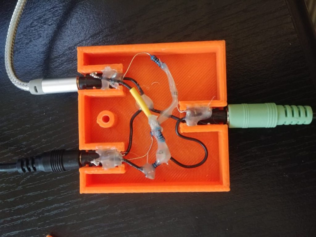
The Guts
My final circuit looks a bit unruly, but it’s completely functional, and I love it! I screwed the lid on and gave it a test drive…
Concluding Notes
I was a bit worried when first testing the device (remember, I’ve never worked with audio circuitry before), but it worked fantastically on the first try. Additionally, the audio quality is excellent, I have observed no noticeable difference with and without the device.
It’s been 3-4 months now since I first built this prototype, and I still use the mixer daily. It sits on my desk and serves as a really nice reminder that, when I get creative and inspired, I can express myself and build some nifty (and occasionally useful) projects. As I move forward into my Clerkship year of medical school and beyond, I hope to keep making the time to get creative and build something. It’s an outlet of mine that never ceases to satisfy.