- NEMA 17 Stepper Motor
- 6x M5-16mm screws for securing to CNC build plate
- 6x M5 nuts
- 1x M3-35mm screw for driving wedge into mandrel
- 1x M3-12mm screw for securing mandrel to stepper motor shaft
- 4x M3-16mm screws for securing stepper motor to mount
- 2x M3-20mm screw for axles on steady rest
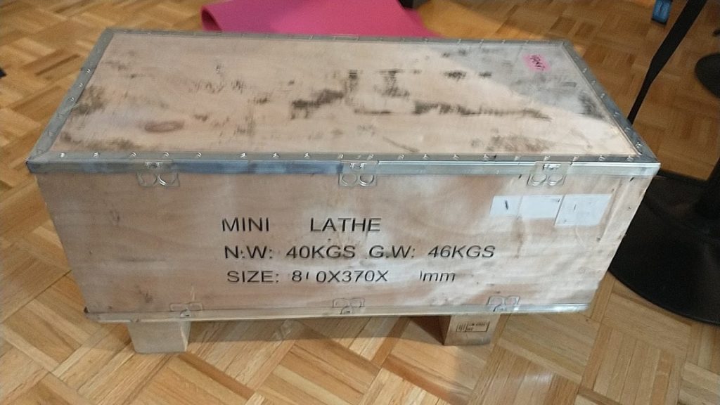
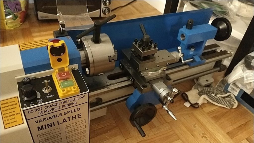
It wasn’t too long ago that I impulse bought myself a mini lathe, inspired by the likes of This Old Tony among other youtube makers. I’ve relied on a scattered hodgepoge of information across the internet in order to get started actually using the thing. Safety came first, but after learning how to spin a chunk of metal at high speed and do so in a way that didn’t make me fear for my life, I turned toward learning how to actually incorporate this awesome new tool into my projects.
I came across the stellar introductory metal lathe tutorials by Blondihacks, and I am incredibly appreciative of Quinn’s ability to present the complex information surrounding proper lathe usage in such a straightforward and thoughtful manner! I would highly recommend checking them out if you’re just getting started with your first metal lathe!
I finally started gaining my footing, and by the time I reached “Metal Lathe Tutorial 16: Your First Project!” I was excited to put my newfound knowledge to good use. While there are many good options for a first project, Blondihacks kept it simple: we would make a ring (in other words, a simple bushing in disguise). I loved the idea, particularly as I had gotten my hands on some beautiful, shiny brass to start turning, I envisioned it would make a lovely ornamental piece.
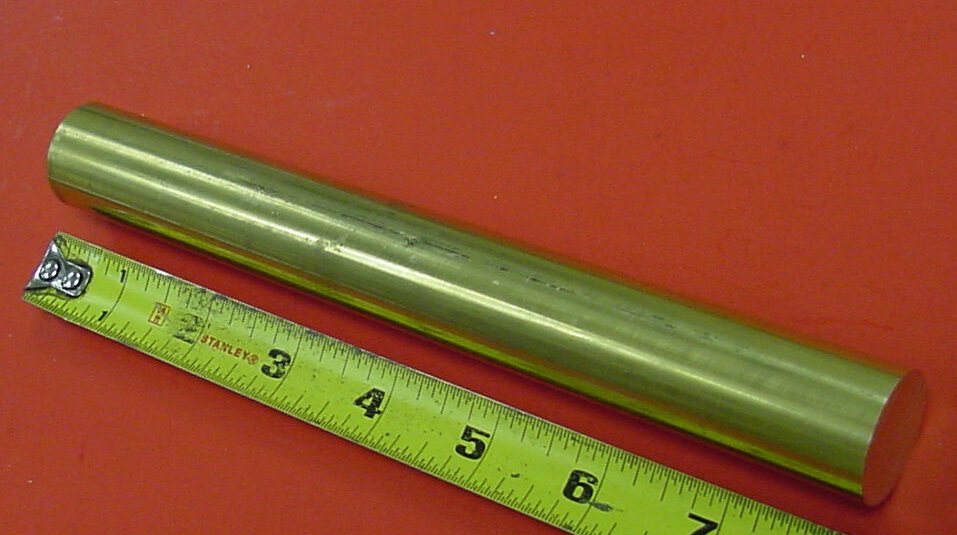
I took the dimensions of my finger, drew out my schematic and organized my order of operations before setting out: facing, turning, center drilling, drilling, parting, filing, deburring, and finally polishing! Before I knew it, I’d turned a rod of solid brass into a shiny ring which slid perfectly onto my finger.
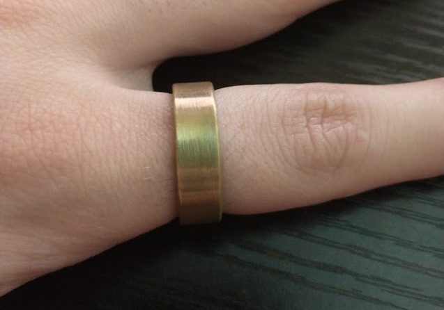
This was very satisfying, and I liked the look of the finished product, but I wanted to take this simple first project to the next level. I wanted to add some decorative elements, to up the wow factor. I also wanted to make another ring as a gift for my girlfriend, and I wanted to give it a bit more of my personal touch, add more of my craftsmanship and love to the final piece.
Design:
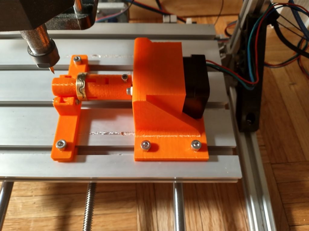
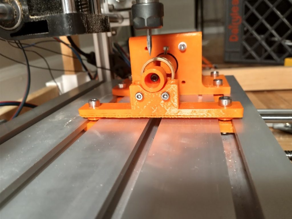
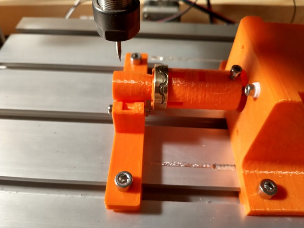
With this in mind, I started searching for solutions which would allow me to use my CNC machine to etchy whatever kind of ornate pattern I desired into the surface of the ring. I envisioned a simple fourth axis using a stepper motor to turn some sort of mandrel which would hold the ring in place during carving. I turned to thingiverse, thinking surely someone else had designed one already. Much to my surpise no such design existed! Determined to make it happen, I booted up Freecad and started designing my own.
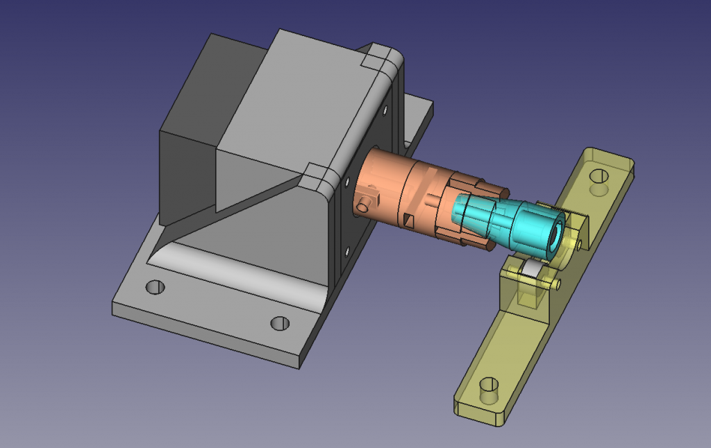
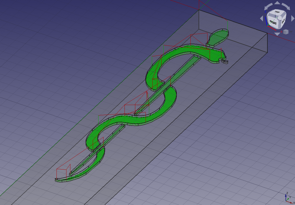
Above you can see the latest version of the FreeCAD model as of the time I am writing this post (v3, although some work still remains to perfect the design). Both the original design files and the STLs can be found on Thingiverse:
https://www.thingiverse.com/thing:4778215
Engraving:
I want to share the steps that I took in order to actually put the above design into action, with the hope that one day it might help someone else looking to do something similar.
I started by finding an SVG of my design. For my first run, I used the staff of asclepius, a symbol of medicine and physicians. I pulled this into FreeCAD using the “Draft” workbench. I then convert to a sketch before switching to the part design workbench to fit it into my body of choice. See the video below for a quick rundown on my methodology.
Once I’ve got my model all setup I head over to the path workbench and create my toolpath. In the current version of freecad the engraver tool does not seem to work for pocketing so I create an endmill tool with a diameter of 0.1mm, which approximates the diameter of the tip of my V-engraver bit. I create a pocket operation with a 0.2mm final depth and 0.1mm stepdown (this is likely very conservative, but better safe than sorry). I use a 1mm/sec feedrate and set my spindle to max RPM.
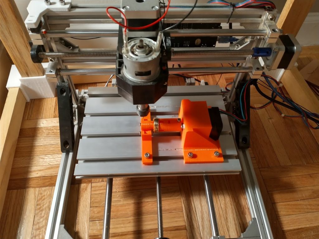
The final step before starting your operation on the CNC mill is VERY IMPORTANT! With this new rotary 4th axis, you must tell your CNC machine how many steps it takes to move 1mm on the surface of your ring. In my case, I am using GRBL to run my CNC mill; additionally my control board does not have a free stepper port to control the 4th axis so I swapped out the y-axis stepper for the 4th axis stepper. Given I am using the Y-axis I went ahead and changed the value of $101= 38, which tells the control board that there are 38 steps required to travel 1 mm on this axis. (note, always a good idea to write down your default value, so you can reset back to it once your done using the 4th axis). I arrived at the number 38 using some simple math. My stepper drivers are set to 1/8th stepping, thus there are 360 * 8 steps per full revolution. I know that the outer circumference of my ring is equal to pi * diamter (in my case pi * 24 ~= 75). Thus I simply calculate (360 * 8) / (pi * 24) ~= 38.
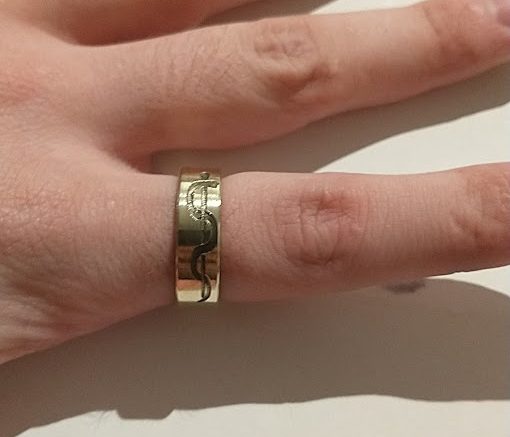
With that final step, we were off to the races. It was smooth sailing from there, with one exception. It seems that there is some imperfection in the leveling of my setup (something I tried to avoid with the steady rest, with mixed results. Thus the bottom half of my design did not engrave as deeply as the top half. The fix was easy in this case, I simply re-engraved this section of the design after dropping my starting Z by 0.1mm. On my next run I hope to avoid this issue altogether by using my CNC’s Z-probe function to map out the height of the ring surface (it’s conductive so it should be fairly straightforward) prior to engraving. I’ll be sure share the results in my next blog post. Until then, stay happy and healthy, and may you have success in all your DIY endeavors!
Doesn’t NMEA 17 have 200 steps per revolution, so your formula should be $101 = 200 / (pi * d) ? Great design by the way.
Enjoyed your blog Jordan! Great content and all. especially loved the video of it working. Could we got some more, maye time lapse of the engraving process?